AD01252
Applications
Board Features
Summary
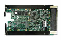
The XRM2-ADC-D10/250 is an XRM2 I/O Module, providing two Analog to Digital converters with 16-bit resolution at sampling rates up to 250Msps.
Aimed at IF/Baseband Signal Sampling, the sampling clock can be sourced from either an external clock source or from a clock generated within the attached FPGA board. An Auxiliary I/O port is provided for use as a trigger input and general purpose signaling. An additional two ports are available for use as high-speed interconnect between boards for synchronisation.
Board Format
Alpha Data XRM2 I/O Module
Environmental Specifications
Temperature Limits:
Code | Cooling Option | Operating Temp. | Storage Temp. | ||
---|---|---|---|---|---|
Min | Max | Min | Max | ||
AC0 | Air Cooled Commercial | 0°C | +55°C | -40°C | +85°C |
Operating Humidity range:
Up to 95% (non-condensing)
EMC Conformity:
FCC 47CFR Part 2
EN55022:2010 Equipment ClassB
For more information on the operating conditions for the different cooling options go to: Alpha Data Environmental Specification Page.
Or read: Alpha Data Environment Specification (PDF).
I/O Interfaces
Interface Type | Qty | Description |
---|---|---|
ANALOG I/O (Front Panel) | ||
ADC | 2 | Dual Analog to Digital Converters Resolution: 16-bit Max Clock Rate: 250Msps Impedance: 50Ω Levels: +10dBm Connector: SSMC Note: exceeding the maximum signal limit may result in permanent degradation of converter performance. |
DISCRETE I/O (Front Panel) | ||
External clock input | 1 | External clock input Impedance: 50Ω Levels: -6dBm to +12 dBm (nominal 0 dBm) Connector: SSMC Minimum usable frequency of 40MHz. Note: Exceeding the maximum voltage limit may result in permanent degradation of converter |
Auxiliary I/O | 2 | Auxiliary I/O Impedance: 4k7Ω (DC Coupled) Levels: +3V3 LVTTL (DC coupled) Connector: SSMC Note: Exceeding the maximum voltage limit may result in permanent degradation of converter |
DISCRETE I/O (PCB Connector) | ||
Synchronisation I/O | 2 | Synchronisation I/O Levels: 1V8 Logic (DC coupled) Connector: U.FL - Limited Access in assembled system User configurable as inputs or outputs, signals direct to FPGA pins (Vccfpio). Note: signals on these connectors must be restricted to 1V8 logic otherwise damage may result. |
Software
Example UCF, HDL files and Application software are provided with the board.
Ordering Code | ||
---|---|---|
XRM2-ADC-D10/250 |
Deliverables
Sales Questions
For any sales questions regarding the XRM2-ADC-D10/250, please e-mail us at:
Technical Support
For any technical questions regarding Alpha-Data products please e-mail us at:
Click to close